

Tel:189-1186-2450
Mobile:189-1186-2450
Email:njzzcg888@163.com
Address:7th Floor, R&D Building, Building 51, Emerging Industries, Nanjing University Science Park, No. 8 Yuanhua Road, Xianlin Street, Qixia District, Nanjing City; Beijing Office: No.1 Zhongliang Road, Daxing District, Beijing, Zhuzong Vanke Plaza
Source:Quasi intelligent sensing Time:2024-06-27
一、Overview
With the increasing electricity consumption in society, the power load of high-voltage electrical equipment carrying the task of delivering large amounts of electricity, such as transformers, transformers, high-voltage switchgear, knife switches, etc., is also rapidly increasing. The connection points between numerous high-voltage electrical equipment in the power grid have become the weakest link in the power transmission system. The prominent issue with this weak link is the connection point(Parts such as the connection between the contact point and the busbar)Fever. As the load increases, it causes the equipment and connection points to heat up and form a vicious cycle: temperature rise, expansion, contraction, oxidation, increased resistance, re heating until accidents occur. According to the National Electric Power Safety Accident Report, only power accidents occur in power stations in China every year,40%It is caused by overheating of high-voltage electrical equipment. Therefore, monitoring the temperature changes of high-voltage equipment and connection points is of great practical significance.
Monitoring the temperature changes of power equipment, timely warning and alarm in case of abnormalities, will effectively reduce the occurrence of accidents, ensure the safe and stable operation of power equipment, and is an important means to ensure the safe operation of power equipment.
The fiber optic online temperature measurement system conducts optical signals through insulated ceramic encapsulated fibers, and detects temperature changes of the measured object by detecting changes in the optical signal. Due to the inherent insulation of the ceramic and optical fibers in the temperature sensing head, as well as the absence and interference of electromagnetic signals, it belongs to intrinsic safety explosion-proof and has a compact size(25xφ8 mm),Therefore, it is suitable for temperature monitoring in all power industries。
二、Purpose of the planThe design requirement of this plan is to be able to monitor the temperature of the incoming and outgoing busbars of the switchgear and cable trays in real time:
1.The high-voltage cabinet temperature measurement system adopts fiber optic grating temperature measurement, and the data is uploaded to the existing temperature monitoring system of the main transformer through the original communication channel;
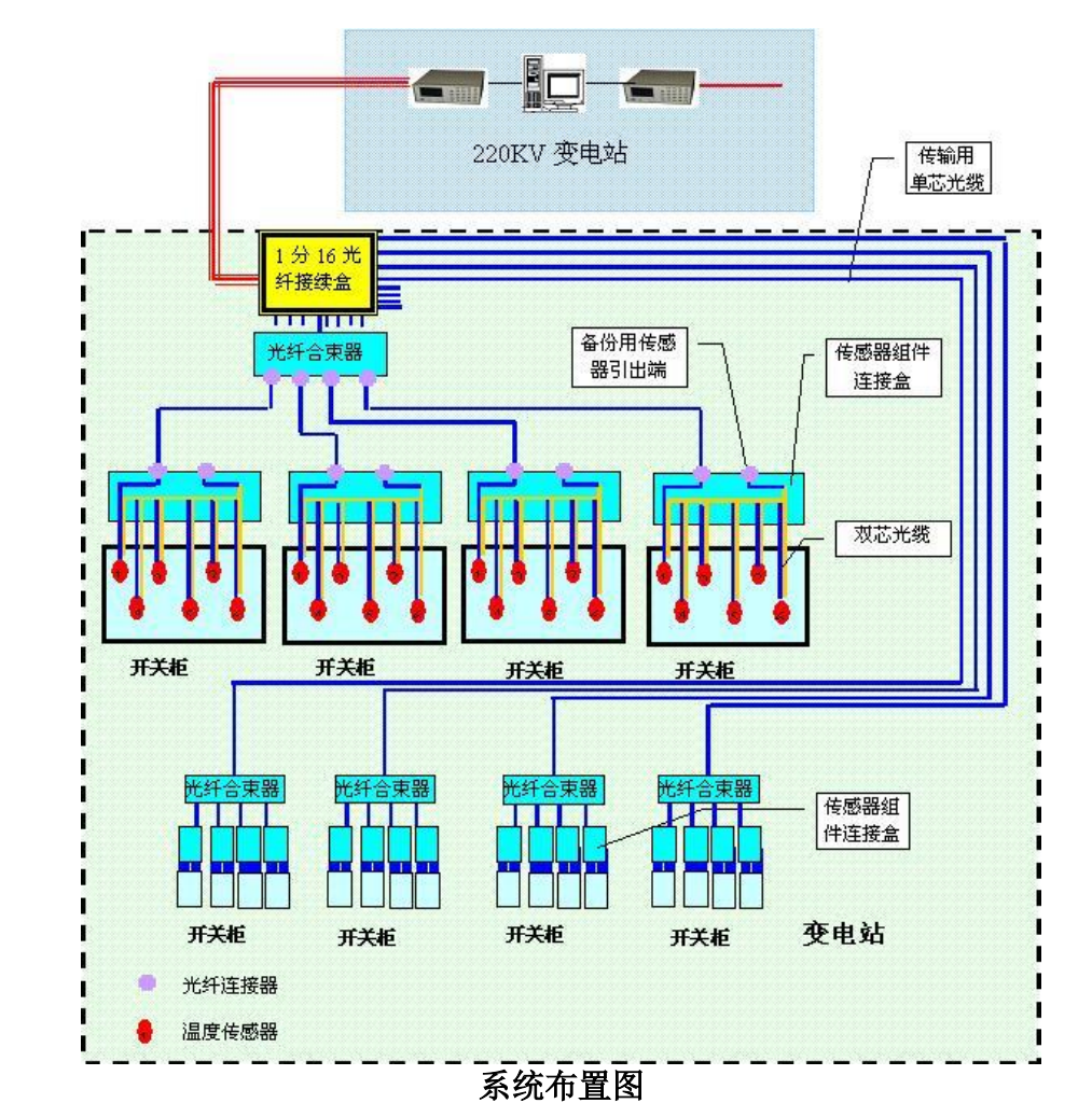
2.Newly designed Salt Substation46Temperature monitoring of the incoming and outgoing busbar of the power switchgear. Layout of each switchgear6Fiber Bragg Grating Temperature Sensor,2Use of surface switchgear1Multiple optical channels. Adopting a star layout method, each temperature sensor adopts a single-sided layout and introduces a fiber optic splitter box. Inside the distribution cabinet, connect the6Sensors are only installed in heat sensitive areas (usually moving contacts or coils, etc.), and couplers are used to connect the sensors on the contacts separately to form parallel connections;2The distribution cabinet uses a signal processor1Monitor each channel to ensure that each distribution cabinet remains independent on the link; Effectively avoiding the severity caused by fiber breakage on the internal links of the switchgear。
3.Cable tray temperature monitoring. The spacing between fiber optic grating temperature sensors is 4 meters, with a total of 12 points deployed. Occupy 2 channels of fiber optic grating signal processor。
4.Graphical interface software, LAN monitoring software。
5.High temperature alarm: If the temperature at the temperature measurement point exceeds the threshold value, an alarm will be triggered, and the alarm threshold value can be set;
6.Data recording: The temperature at each temperature measurement point can be saved, the recording time can be adjusted, and the minimum recording time interval is 60 seconds;
7.Query of system historical alarm records;
8.The measured temperature range is -40 ℃ to 130 ℃;
9.The measured temperature accuracy is ± 0.5 ℃, the temperature resolution is 0.1 ℃, and the response time is less than 40 seconds;
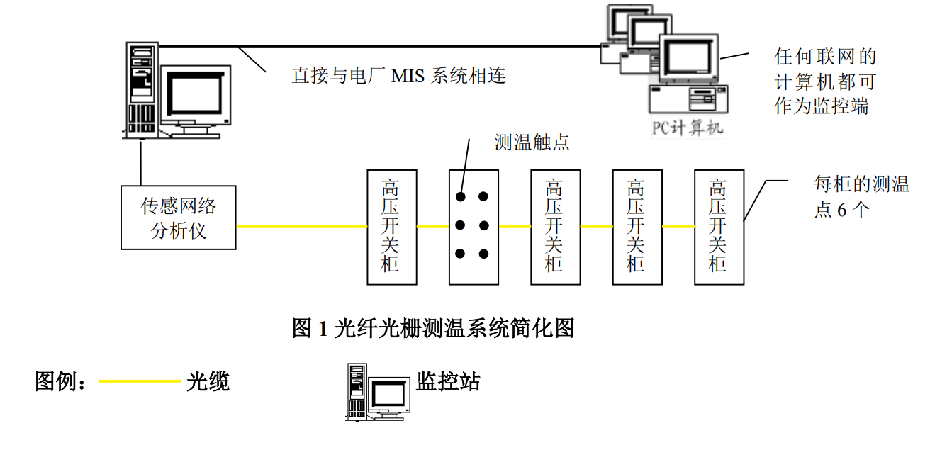
三、System composition and descriptionThe fiber optic grating power cable temperature measurement system adopts a fully digital network structure, which improves the anti-interference ability of the entire system. The system adopts a star shaped mesh topology structure and is connected to sensors distributed in cable trenches and switchgear through a fiber optic analyzer. Each channel can be connected with 30 intelligent temperature sensors, making it easy to install, maintain, and expand the system. Fiber optic material transmission and fiber optic sensor monitoring ensure reliable operation of the system in harsh environments with no electricity on site. The following diagram is a simplified structure diagram of the alarm system
:
The online temperature detection system scheme for switchgear includes the following interrelated subsystems:
1、Sensors and transmission systems
This system applies advanced quasi distributed fiber optic grating sensing technology, which converts the measured temperature value into an optical signal that is easy to record and reprocess through fiber optic grating sensors. Due to the fact that the signal output from the sensor is an optical signal, it can be directly transmitted over long distances through optical cables. The excellent environmental resistance of fiber Bragg gratings also provides reliable guarantees for long-term safety monitoring。
2、data acquisition system
The function of the system: The optical signals generated by fiber optic grating sensors are transmitted remotely through optical cables, and then directly recognized and converted into physical quantities through the fiber optic grating sensing network analyzer placed in the monitoring room. The recorded data can be displayed, recorded, saved, or directly entered into the monitoring database on the computer terminal。
3、Monitoring data management software system
The purpose of this system is to effectively store various types of data through appropriate organization based on the characteristics of each monitoring project. Minimize data redundancy while ensuring necessary information storage. This management system can easily obtain data from the data volume system, and the data can be easily accessed by different users。
4、Main performance indicators of detectors
Temperature measurement range: -40~200 ℃
Maximum temperature resistance: 220 ℃
Temperature resolution: 0.1 ℃
Accuracy: ± 0.5 ℃
Response time:<10S
Optical cable transmission distance:<40km
The temperature sensor can withstand high voltage of ESD ± 500000 V and operate 24/7。
Service life: 150000 hours (over 15 years)
5、Main technical specifications of signal processor (fiber Bragg grating demodulator)
Number of channels: 8, 16, 24, 32
Maximum number of detectors deployed per channel: 12
Working power supply: 220V AC
Environmental temperature: 0 ℃~40 ℃
Test cycle time:<2S
四、Scheme DescriptionExample explanation:
The distance between substation switchgear room A (24 switchgear faces) and substation switchgear room B (24 switchgear faces) is 500 meters, and the distance between substation switchgear room B and switchgear room C (10 switchgear faces) is 30 meters; We are considering online monitoring of the temperature of the switchgear, with 6 points on each side of the switchgear, totaling 58 switchgear panels and 348 sensors installed。

1、This system consists of sensors and transmission systems, data acquisition systems, and monitoring and management software systems。
2、Sensors and transmission systems consist of fiber optic sensors and fiber optic communication networks。
3、The data acquisition system consists of two fiber optic sensing network analyzers, exchange routers, main industrial control computer, sound and light alarm, printer, etc。
4、The sound and light alarm communicates with the industrial computer through the RS232 port。
5、The printer is connected to the industrial computer through a parallel port。
1、Sensor installation method:
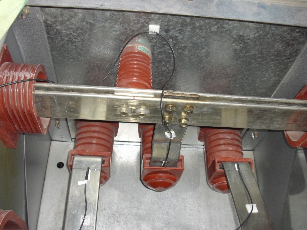
The fiber optic sensor is installed on the six fixed contacts of the cabinet, and is mounted on the static or dynamic contacts of the switchgear using high-temperature resistant epoxy adhesive or metal clamps. The minimum bending radius of optical fibers transmitted inside the cabinet is greater than 3 centimeters.
The system adopts fiber optic loop function, and each string of fiber optic sensors has two testing fiber optic ports in the main monitoring room. When the system is good, both ports can obtain correct testing values, and in case of abnormalities, it can improve the reliability of the system to a certain extent.
After the fiber optic cables of the sensor connection components are laid out in the cabinet, place them into the switchgear。
The appearance of the sensor is shown in the figure. Apply an appropriate amount of thermal insulation adhesive to the temperature sensing area and place it on the surface of the measured object。

The sensor is installed on a 10kV/35kV busbar, and the optical cable should be routed along the insulation rubber sleeve of its own busbar. Fix the sensor tightly with a positioning suction cup 10cm away from the installation, and try to avoid the optical cable winding inside the cabinet as much as possible. The optical cable of the coil should be fixed neatly, and after installation, it is required that the sensor signal is normal and safe without any hidden dangers。


 189-1186-2450
 7th Floor, R&D Building, Building 51, Emerging Industries, Nanjing University Science Park, No. 8 Yuanhua Road, Xianlin Street, Qixia District, Nanjing City; Beijing Office: No.1 Zhongliang Road, Daxing District, Beijing, Zhuzong Vanke Plaza
Copyright© All Rights Reserved for Intelligent Sensing SuICPB No. 2024111040 技术支持:中企云达